I am a mechanical engineering student at the Rose-Hulman Institute of Technology with internship experience at SpaceX and L3Harris Technologies. The work here shares a theme: I like to design things, build them, and test them, whether that is an engine on a test stand, a lander taking shape in CAD, or software that speeds up engineering work.
- Education
- Rose-Hulman Institute of Technology, B.S. Mechanical Engineering, expected May 2028
- SpaceX
- Mechanical Engineering Intern, LC-39A, 2025
- L3Harris Technologies
- Mechanical Engineering Intern, 2025 and 2026
- Primary Engineering Inc.
- Mechanical Engineering Intern, 2023–2024
Hydrogen/Oxygen Rocket Engine
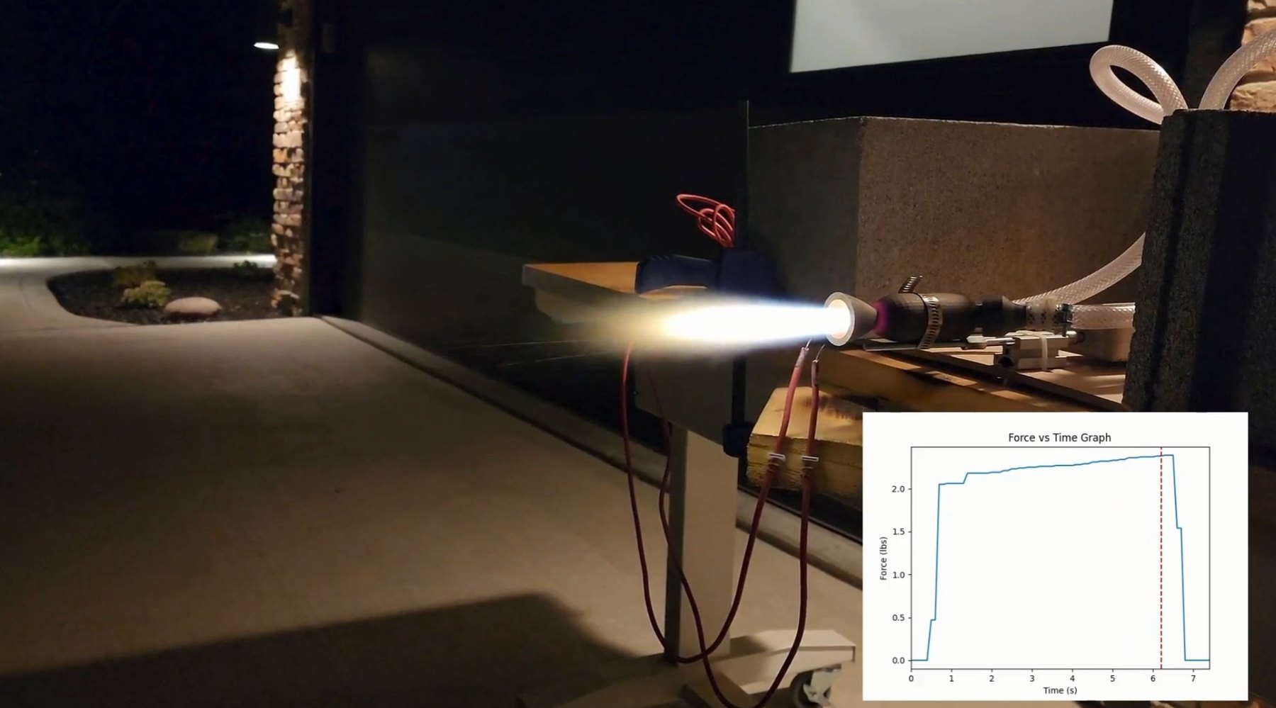
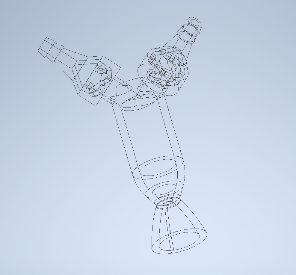
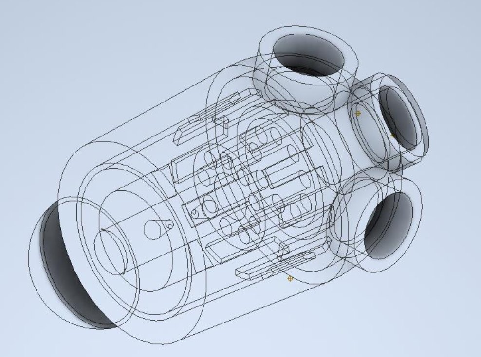
I designed, built, and successfully hot-fired a pressure-fed, gaseous hydrogen/oxygen rocket engine producing 3 lbf of thrust. The engine is built around an additively manufactured thrust chamber assembly, with propellants delivered from regulated gas supplies and thrust measured live on the stand. The firing at the top of this page is one of those tests.
- Propellants
- Gaseous hydrogen / gaseous oxygen
- Cycle
- Pressure-fed
- Thrust
- 3 lbf, measured on the stand
- Fabrication
- Additively manufactured thrust chamber assembly, printed by an outside vendor
- Scope
- Design, test stand, instrumentation, and test conduct
Engineering Agent
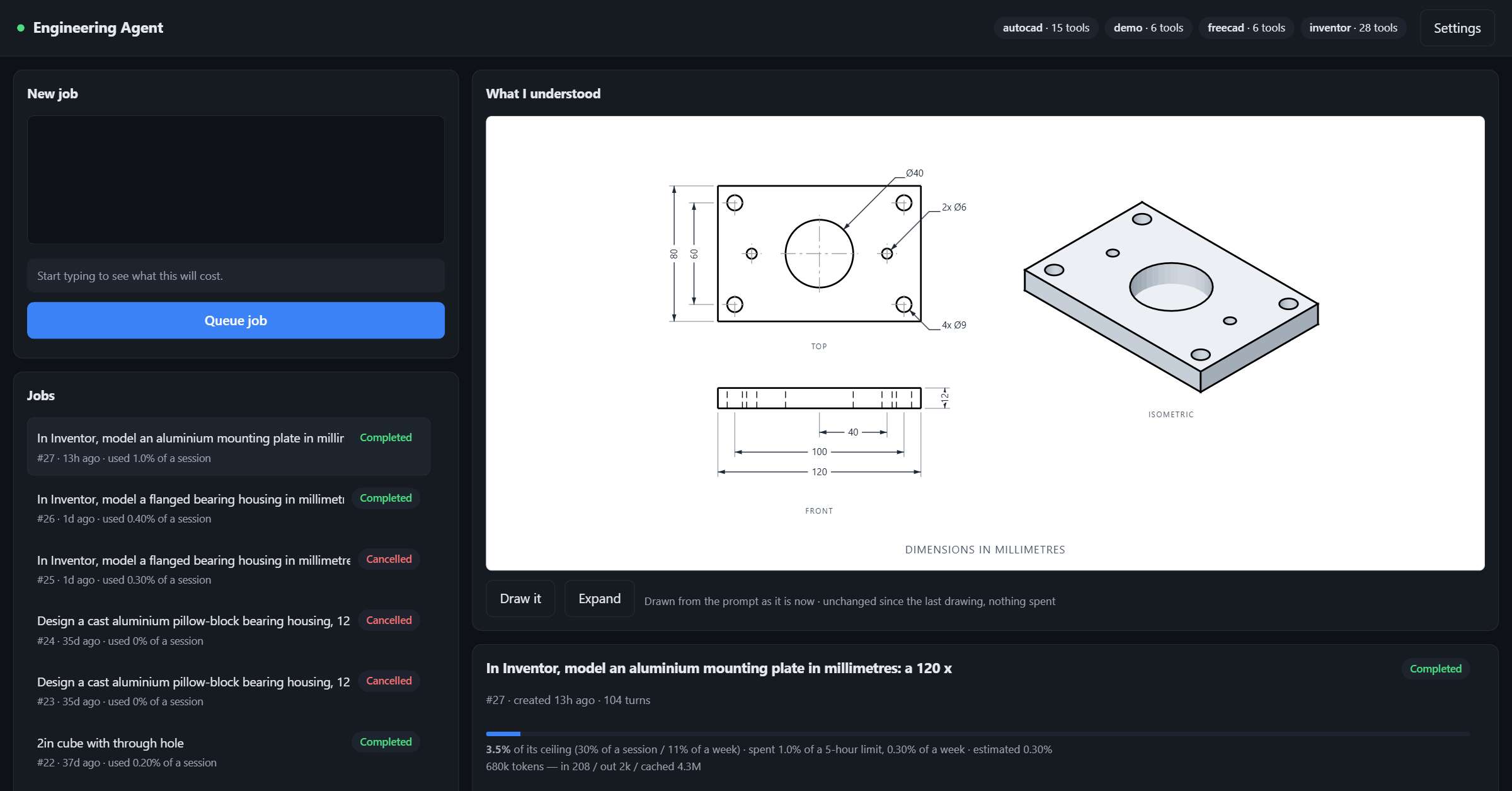
I am developing Engineering Agent, a Python program that takes user prompts for CAD models and uses both Claude and local modeling applications to produce CAD models with minimal user input. The program checks and corrects the work of the AI and provides the user the means to course-correct the AI easily if it misinterprets the user prompt. I am planning to extend the program so it can run simulations on the parts it produces.
Lander Design Team & Rocketry Leadership
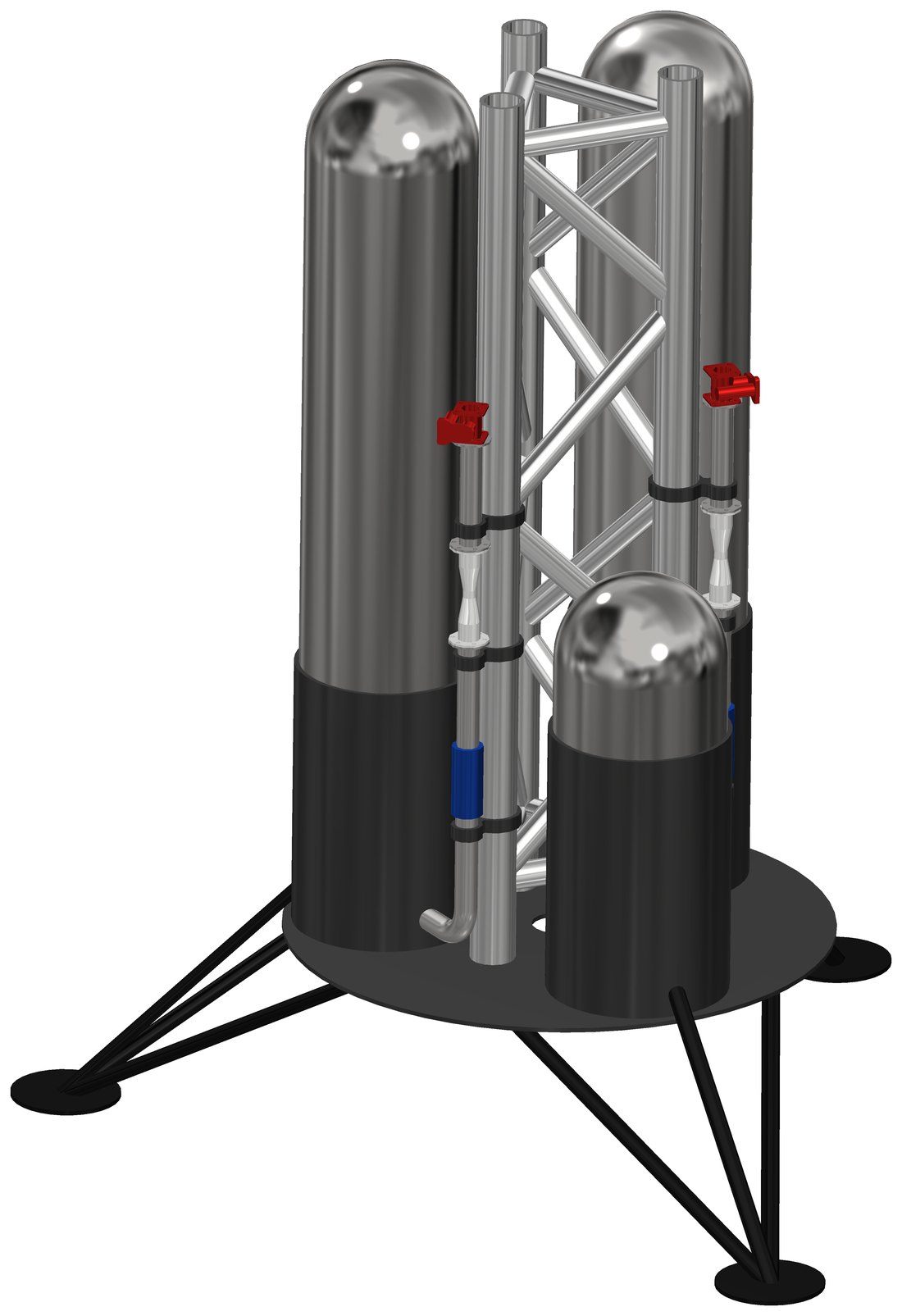
I lead the lander design team on Rose-Hulman’s rocket team and serve as the team’s treasurer. The lander is very early in its development, and the CAD below is an early concept.
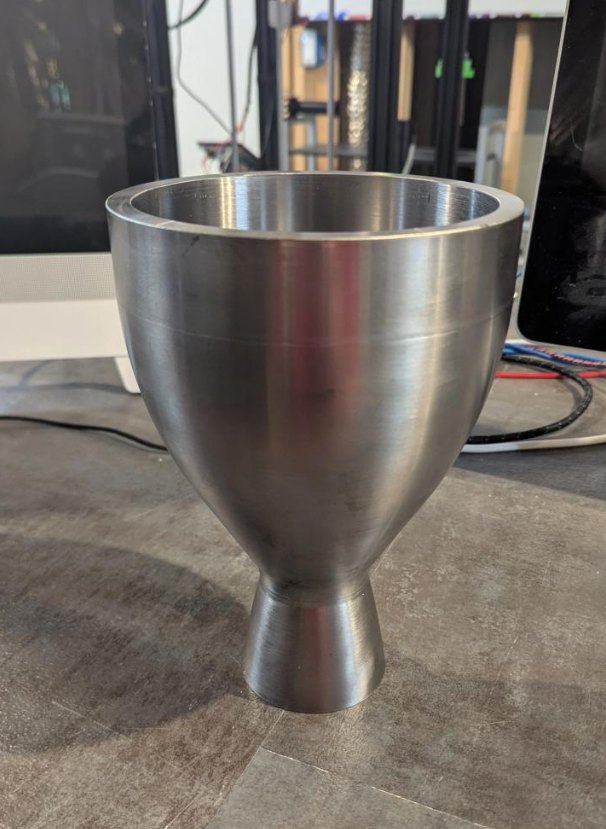
Before transferring to Rose-Hulman, I founded and led the rocket team at Purdue University Fort Wayne, taking a liquid-fuel propulsion project from scratch to a machined nozzle, shown below.
Sound-Suppression Vent
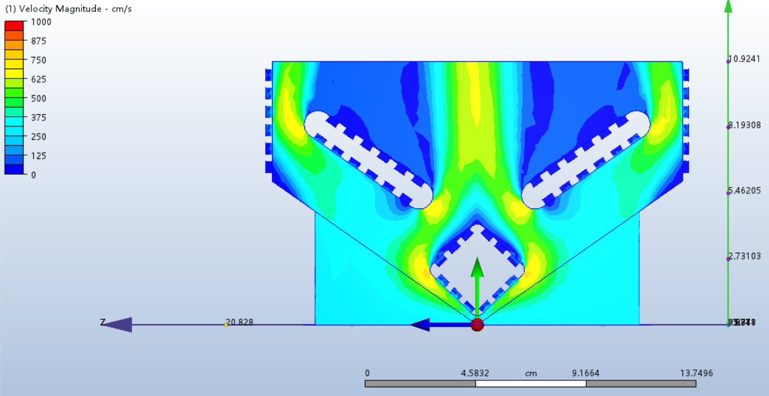
I designed and built a sound-suppressing vent: a flow path lined with slotted inserts intended to hold sound-absorbing foam. The CFD velocity field below was part of the design work, checking how the flow distributes through the vent and around the inserts. In testing, the vent managed only a barely noticeable drop in noise. The concept ultimately proved impractical, but designing, building, and testing it taught me a lot about acoustics, fluid simulation, and physical testing.